Tuesday, April 30, 2013
2014 Chevrolet Corvette Stingray Owner Manual
 |
| Google Images |
Owner Manual 2013 Chevrolet Corvette Coupe

Friday, April 26, 2013
2012 BMW 550i 5 Series Owners Manual Guide Pdf
 |
| Google Images |
Friday, April 12, 2013
2008 Mazda MX 5 Miata Owners Manual
Notes About This Manual Keep this handbook within the glove field as a to hand reference for the secure and stress-free use of your Mazda. Should you resell the car, leave this handbook with it for the subsequent owner. All specifications and descriptions are correct at the time of printing. Because improvement is a constant intention at Mazda, we reserve the precise to make changes in specifications at any time with out notice and without obligation. Event Data Recorder This vehicle is provided with an event data recorder. In the event of a crash, this instrument records information associated to car dynamics and securety techniques for a brief time period. These knowledge can assist present a greater figuring out of the cases during which crashes and accidents happen and lead to the designing of securer automobiles. Air Conditioning and the Environment Your Mazda’s genuine air conditioner is stuffed with HFC134a (R134a), a refrigerant that has been found to not damage the earth’s ozone layer. If the air conditioner does now not operate correctly, seek the counsel of an Authorized Mazda Dealer. Please keep in mind that this manual applies to all editions, equipment and choices. As a result, you could also in finding some rationalizations for equipment now not installed in your automobile.
Download: 2008 Mazda CX-9 Owners Manual
Thursday, April 11, 2013
2003 HYUNDAI TIBURON GS R
The bucket seats prove very comfortable and the driver enjoys a very good driving position. Aside from that,headroom is limited for people of average height and up, while visibility is awful from ¾ behind, from ¾ forward, and toward the front right side due to the blind spot created by the side-view mirror. Further, claustrophobic people will be somewhat uneasy since the belt line is quite high. Elsewhere, the side-view mirrors that extend a bit toward the rear make life difficult for those of average height and below. Lastly, the rear spoiler can interfere with visibility out the back. It almost goes without saying that the rear seats are only for small people—and even then, just for short trips—since there is precious little headroom and legroom. Actually, this area is much more useful for storage than for passengers. The trunk is rather roomy and easily accessed thanks to the lift gate’s large opening and the reasonable liftover. Load capacity can be increased by folding down the rear seat’s 50/50-split seatback.
Download: 2003 HYUNDAI TIBURON GS-R
Wednesday, April 10, 2013
BHEL Recruitment Paper 2
Mechanical Advantage


Secrets 2013 Ford Taurus SHO Sedan Dynamic

Style: Sedan.
Seating Capacity: 5.
Base Price: $32,000.
Price as Tested: $45,285.
Engine: 3.5 liter twin-turbocharged EcoBoost V6 – 365-hp at 5,500 rpm and 350 lb-ft of torque at 1,500 rpm.
Transmission: 6-speed automatic with paddle shifters.
0 to 60 mph: 5.2 seconds.
Top Speed: 133 mph.
Curb Weight: 4,350 lbs.
Fuel-economy: 17/25 mpg (city/highway).

 |
| 2013 Ford Taurus SHO Interior |

Friday, April 5, 2013
Audi A8 Painting Stock Calipers
Things You Will Need: Caliper Paint Kit (or Paint, Brake Cleaner, and Bushes), Masking Tape, Wire brush and/or Sandpaper, Rag, Jack and Jack stands, Socket Wrench, Decal (if desired)
Mod Time: 3 hours
Difficulty (1 to 5, 5 being the most difficult): 1 – Very easy, takes a bit of time but straight forward.
Step 1 – Preparation
Loosen the bolts off and proceed to jack up every corner of the car.

Once the car is off the ground, remove all four rims.
In order for the paint to last, you must thoroughly clean the calipers.
Spray the calipers with the cleaner, allowing it to air dry. Use the wire brush and sandpaper to clean off the rust.
Then respray the calipers with the cleaner and wipe them down with a rag.
Using the masking tape, cover all areas you do not plan on painting. It is important to cover all rubber parts and the brake bleeder screw.
Step 2 – Painting
Stir the paint real well. Brush on thin coats.
Wait 10-15 minutes before applying subsequent coats.
Repeat this process until you have consistent coverage and are happy with the look.
Step 3 – Waiting
The paint requires a curing time, and this will vary by what you use. Check the can for specific information.
Move onto the next caliper as the one you just completed dries.
Once you have painted all four calipers, you can remove the masking tape.

Step 4 – Decals (If Desired)
Some like to place a decal on the caliper to give that special look.
Once the paint is dry, line up the decal and place it on the freshly painted caliper.

You may want to coat the edges in clear coating to help hold it on, but this is not necessary. Covering the whole sticker may cause damage to it, so be careful.
Step 5 – Waiting
You can now replace the rims and lower the car.
Make sure you re-torque the bolts to their proper specifications.
Be careful when replacing the rims to not hit the calipers. The paint has not fully cured so it may be fragile.

Stand back and enjoy the new look, no longer will you see rusted calipers behind your rims. When cleaning your ride make sure to spray and wipe them down to maintain that high-gloss finish.
Audi A4 B5 A4 1 8Tq Clutch Replacement
DISCLAIMER: This information is presented merely as a guide. Due to changes from year-to-year and options-to-options it may not be totally accurate. I can not be held responsible for anything that happens as a result of using this guide.
This is not something that should be attempted by someone who has never worked on a car, or has little experience with them.
If you use this guide, I only ask two things:
1. Accept the disclaimer,
2. Provide Feedback - comments/tips/problems/differences.
There, now that thats out of the way, lets begin.
Tools needed

- Jack
- Jackstands
- Transmission jack - I borrowed mine from my uncle, its from Sears, and has an angle adjuster and strap to keep the trans on the jack.
- Impact wrench
- 6mm allen socket
- 7mm allen socket
- 8mm allen socket
- 6mm allen wrench
- 8mm allen wrench
- 10mm socket (3/8" drive)
- 13mm socket (3/8" drive)
- 15mm shallow socket (3/8" drive)
- 15mm deep socket (3/8" drive)
- 15mm wrench
- 15mm "shorty" wrench
- 16mm shallow socket (3/8" drive)
- 16mm deep socket (3/8" drive)
- 16mm wrench
- 16mm "shorty" wrench
- 17mm shallow socket (3/8" drive)
- 17mm deep socket (3/8" drive)
- 17mm impact socket (1/2" drive)
- 17mm wrench
- 17mm "shorty" wrench
- 18mm wrench
- 22mm wrench
- 3/8" drive ratchet
- 12" extension w/swivel end
- 6" extension
- 3" extension
- screwdriver
- phillips screwdriver
- Torque wrench
- Plug for coolant hose (I used a 3/8" bolt)
- 6 point T40 Torx bit
- 12 point T40 Torx bit - special tool???
- Loc-Tite
- Patience
- Common Sense
- fan (gotta keep cool, right?)
If youre planning on changing the trans fluid, there are some special tools required. On my car it required a 17mm allen wrench (fill plug) and "3357 triple square socket" (drain plug) I bought the 3357 from http://www.zelenda.com and made the allen from a 17mm bolt welded to an old 1/2" drive socket.
I, of course, had these sitting in my toolbox, in the back of my car, 180 miles away :( So I made a new fill plug remover by welding a nut to bolt, and using a wrench on the nut, which turned the bolt, which turned the fill plug. I then picked the trans up and drained it through the fill plug. I used Redline MTL (75w90) fluid, it takes 2.9 quarts.
If you do change the fluid, do it after youre done. Wouldnt want to take the chance of spilling fluid in the area you will be working in/on for the next several hours.
Parts
- Flywheel
- Clutch
- Pressure plate
- Flywheel bolts (shorter than stock bolts)
- Pressure plate bolts (same as stock bolts)
- Throwout bearing
- Clutch alignment tool - not necessary, but helpful
- Driveaxle or driveshaft bolts - in case you muck up the ones you have.
- New lock-nuts for the turbo - Bentley manual says to replace them, I didnt
- New drive axle and driveshaft seals - Bentley manual says to replace them, I didnt
Instructions - Removal
I am following the Bentley manual for the most part. There are some steps I skipped, some that need to be added, and others that can be done differently. Im posting the steps and providing more info with them. If you are attempting this, you should have this manual already. It contains many other things, especially the required torque values for the bolts.
1. Disconnect ground cable from battery - 10mm
2. Remove driveshaft - ignore this step, its not necessary
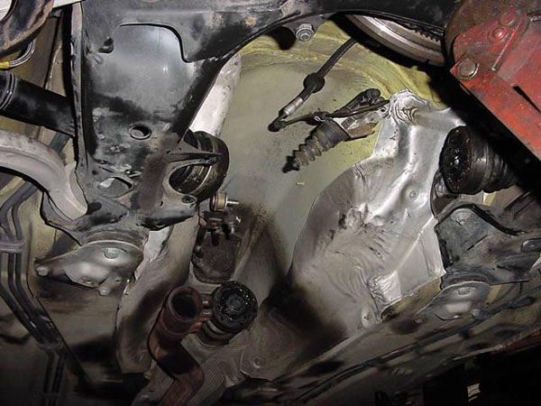
3. Remove airbox - see pic
- Disconnect MAF connector
- Disconnect Power Output Stage connectors (see pic - 1)
- Disconnect Solenoid Valve for Wastegate Bypass Regulator Valve connector (see pic - 2)
- Disconnect EVAP canister purge regulator valve connector (see pic - 3)
- Disconnect hoses
- Pull airbox out
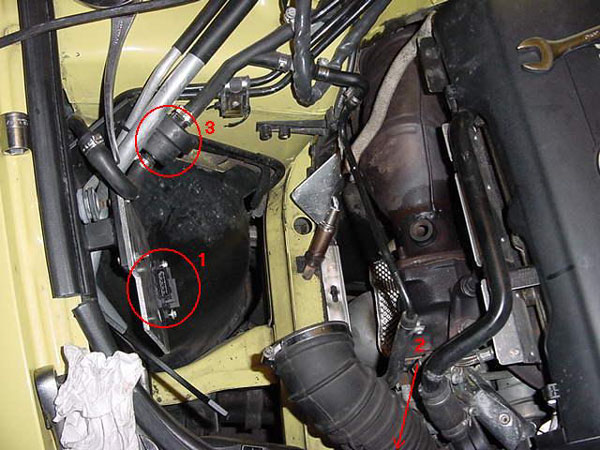
My car has a custom cone air setup, which is why the POS is mounted on aluminum and bolted to the fender.
4. Remove coolant tank and set aside
- remove three screws from top (phillips)
- Lift up and disconnect sensor from bottom (careful)
- remove top coolant line and plug.
- Leaving the bottom hose (big hose) connected, rotate the tank around about 135 degrees and lay it down
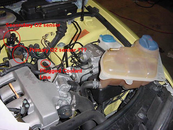 |
| Coolant tank sitting position and O2 sensor connectors. |
5. Disconnect second O2 sensor connector from under the coolant tank (leftmost connector - see pic) and free the wiring from any ties.
6. Remove O2 sensors. The manual does not say to do this, but I did it. Trying to remove the cat is difficult enough without having to worry about breaking the O2 sensors too. Takes a 22mm wrench and a little elbow grease. Youll probably have to track down the connector for the primary O2 sensor, or you might possibly twist the wires enough to break them (mine didnt break, but the jacket/insulator on one wire opened up.)
7. Remove nuts from cat-to-turbo connection. Three 17mm nuts. The shorty wrench will come in handy for the bottom nut.
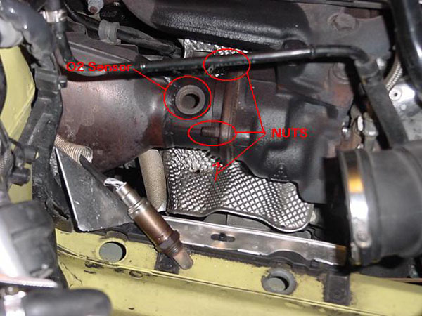 |
| The nuts and O2 sensor have been removed |
8. Remove trans-to-engine bolts that you can get to from above. I think there were three accessible from above (left, middle, and right) 16mm.
9. Remove engine pan/cover from underneath - 10 screws: 3 front, 3 back, 2 in each wheel well.
10. Remove bracket for engine pan/cover - 2 bolts (13mm I think)
11. Jack car up and put on jack stands. Im not really sure of a good place to put the jackstands, I now have two slight dents in the floorboard of my car.
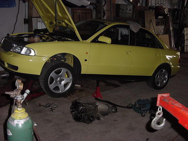 |
| Car up in the air. Possibly bad spot for jack stands. |
12. Remove heatshield from passenger side drive axle. Three 6mm allen bolts, two accessible with an allen socket (left and right) and the top bolt requires an allen wrench.
13. With the car supported on jack stands, place slight pressure on the trans with a jack.
14. Unbolt passenger side mount/support (leave mount connected to support) - two 13mm bolts, and three 8mm, again, two accessible with an allen socket (left and right) and the top bolt requires an allen wrench. Also remove the spring mount from the downpipe. You can let the jack pressure off the trans now, it will be fine without.
15. Loosen clamping sleeve on downpipe-to-exhaust connection. Youre supposed to be able to slide the clamping sleeves forward, but I couldnt get it to budge, and ended up pulling the downpipe out of it instead.
16. Remove the cat/downpipe by pulling it out from under the car. I made the mistake of trying to get it out from the top. I did finally get it with a lot of swearing and fidgeting. Oh well.
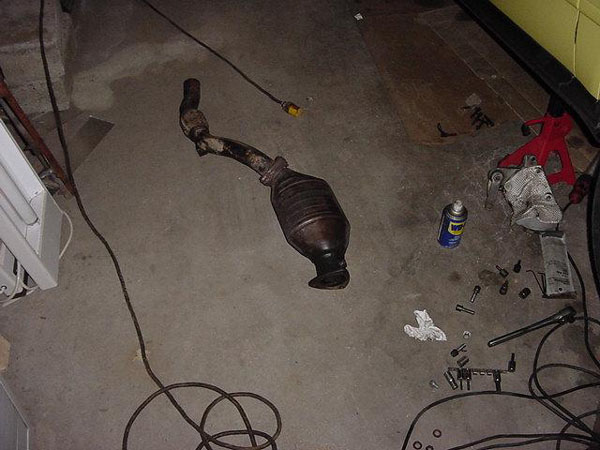 |
| Catalytic converter and downpipe |
17. Remove RPM sensor from transmission. My car did not have this. If it did, it would be located on the drivers side of the transmission, above the flywheel (about the two oclock position if looking at the front of the trans).
18. Now the fun part (1st of many) Disconnect the driveaxles. The shafts are bolted in with six 12 point torx-head bolts. I was able to use a regular 6point T-40 torx bit to remove them, but I highly recommend trying to get the 12 point bit to reduce the chance of rounding one of these things off.
19. Disconnect Speed sensor and reverse light connectors on drivers side of the trans. Make sure no other connectors are attached.
20. Remove starter, two 16mm bolts and one 6mm allen bolt. The wires can stay connected. This can be done one of two ways: The long and painful way, or the short and painful way.
- Long way: Remove bumper, remove A/C belt, remove A/C pump, remove starter.
- Short way: Attempt to get at 6mm allen bolt with an allen wrench by maneuvering your hand and arm through the A/C lines. When finally out (wait until you have to put it back in) remove the two starter bolts, slide the starter forward and attempt to lay it aside somehow.
21. Disconnect shift rod, one 10mm bolt
22. Disconnect shift pivot rod - one 8mm (may have been 6mm, not sure) allen bolt. Space is tight requiring the use of an allen wrench. When its out to the point that the allen wrench hits the trans tunnel, remove the allen wrench and try turning the bolt or washer on the backside with your fingers.
23. Remove the heat shield for the driveshaft. My car did not have this.
24. Remove the driveshaft from the trans - six T-40 Torx bits, let it hang on the heat shield.
25. Remove the four engine-to-trans bolts on the bottom (all 16mm), and there should be just two left holding it together afterwards.
26. Place transmission jack under the trans and put pressure on it.
27. Remove drivers side trans mount-to-support bolt (8mm allen bolt), leave the support bolted to the trans.
28. Remove the last two engine-to-trans bolts.
29. slide trans and trans jack back just enough for the bell housing to clear the pressure plate.
30. Lower trans just enough to get access to the clutch slave cylinder. While lowering the trans, DO NOT LET THE INPUT SHAFT HIT THE PRESSURE PLATE "FINGERS" The clutch cylinder is held in with a 6mm allen bolt, and will take a little bit of wiggling to get it out. Careful, its made of plastic. Do NOT remove the line, and do NOT press the clutch pedal.
31. Make sure all drive axles are clear of the trans and lower it. You might have to pull the trans off the jack to slide/drag it out from under the car, or you can just leave it under the car, and slide it out of the way.
 |
| Empty trans tunnel. |
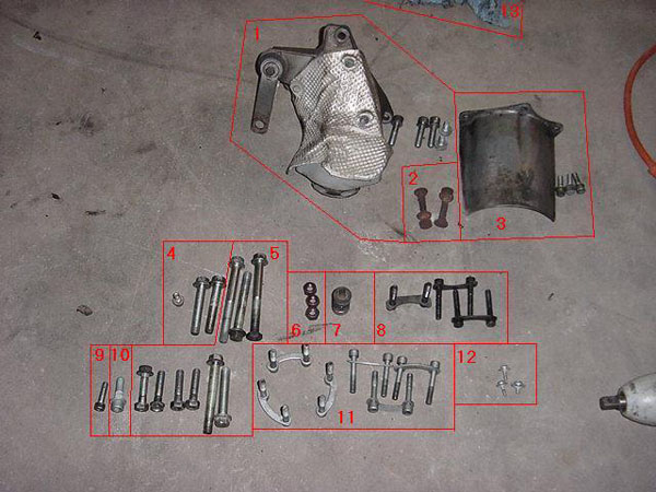 |
| Parts removed |
1 - Passenger side trans mount and related bolts
2 - Exhaust clamp bolts
3 - Passenger side drive axle shield and related bolts
4 - Starter Bolts
5 - Engine-to-Trans bolts
6 - Turbo-to-downpipe nuts
7 - Exhaust hanger spring
8 - Driveshaft bolts
9 - Clutch slave cylinder bolt
10 - Driver side trans support-to-mount bolt
11 - Drive axle bolts
12 - Coolant tank screws
13 - Just a rag, ignore it :)
Removing the clutch/flywheel
1. Remove the six 6mm allen head bolts from the pressure plate and remove it and the clutch plate. A screwdriver might be needed to gently pry it off. Careful, the pressure plate is the only thing holding the clutch plate in, and it WILL fall if youre not paying attention.
2. Bust out the impact wrench to loosen the six 17mm flywheel bolts. You probably dont need the impact, but you will spend a very long time trying to get the bolts loose without one.
Installing the clutch/flywheel
1. Look at the flywheel and youll notice the bolt holes are irregular. The flywheel only goes on one way. when you have all 6 bolts in, torque them down. I held a screwdriver between a flywheel tooth and the block while tightening. The manual calls for 44 ft lbs + 90 degrees. The shorter bolts for the new flywheel probably dont require the 90 degree turn. Check with APR to be sure.
2. Put the clutch disk and pressure plate on, the clutch disk has to go in a certain way (the taller middle side goes towards the pressure plate) Start putting the bolts in, but dont tighten yet. You need to center the clutch disk in the pressure plate. I eyeballed it since I didnt have the alignment tool. Torque the bolts in stages in a triangular fashion when its centered.
Time it took me to get this far, about 7 hours.
Take a break, the hardest part is about to begin.....
1. With the transmission on the transjack (if it has an angle adjuster, make sure its on the correct side), slowly lift it into place, making sure that nothing is in its way. You will need to match the angle of the engine with the angle of the jack. You will have to slide the trans in a little, jack it up, slide it in, jack it up, etc until the trans is aligned withe the engine. It may help to have a greater angle on the trans, and when its lined up, equal the angles out. DO NOT LET THE INPUT SHAFT HIT THE PRESSURE PLATE FINGERS. If one of them bends, bad things happen.
| |
| Jack on transjack - notice the the dents from the jackstands. |
2. Put the clutch slave cylinder back on. Trust me on this one, do it now, before the trans is connected.
3. Now the fun part, inserting the trans. Mine slid right in, but if it doesnt, remember patience is the key. Put the trans in gear and try rotating the driveshaft end. this rotates the input shaft, and may help align it. If all else fails, pull the trans out (careful if the slave cylinder is bolted on), and check to make sure the clutch is still centered.
4. The trans probably wont slide all the way in. Get it in enough to get a bolt started on either side (start with the bolts that go through the guide pins.
5. Basically, everything else is the opposite of removal, just a little more difficult.
Reassembly time, about 8 hours.
Things to avoid (aka what I did wrong)
1. Remove the cat/downpipe from the bottom. It will come out from the top with a lot of struggling, yanking, and cursing, or it will drop right out the bottom with slight maneuvering.
2. when putting the transmission in, I got the shifter pivot arm caught between the trans and the hull, and bent it straight. I found this out after I had everything in, and realized I couldnt shift into 1st, 3rd, or 5th. The shift rod wouldnt come back far enough because it hit the shifter pivot arm. A jack and a 2ft long 2x4 promptly bent the arm back into shape :)
3. I tried to put the clutch slave cylinder on after the trans was installed. I could not get it to compress enough to install. I had to crack open the bleed screw and then push it in (I had a hose and container hooked up to catch the fluid), and then bled the clutch system afterwards (not a big deal though)
4. My APR flywheel/clutch was used and didnt have any bolts with it. I had to cut 5/8" off the end of the flywheel bolts in order to use them.
Notes/Comments/Suggestions:
Plan on a weekend for this job. Start Friday night, and if all goes well, you should be done Saturday night, or Sunday morning.
I started Thursday night about 10pm, worked until the trans was out at 4am. I started again Friday night about 9pm, worked until 4am and finished up a couple little things Saturday afternoon.
I should also say that my clutch and center Torsion were replaced about 10 months ago (25K miles) so I didnt have any stubborn bolts.
You might want to start by trying to bust the driveaxle and driveshaft bolts loose first. These will probably be the toughest bolts to get out. If you cant get them out, theres no sense in continuing, and it would suck to have to put everything back together
1. hit it with a hammer a couple times
2. If it rounds off inside, try pounding an allen bit into it.
3. You could try grinding a slot in it, and using a screwdriver.
4. Try Vise Grips
5. Youll notice that there is a connector between pairs of bolts. If its the right bolt of the pair, you can use this connector as a lever (assuming the left bolt is out of course)
Thursday, April 4, 2013
2004 Odyssey Online Reference Owner’s Manual
Afterwards, keep this owner’s manual in your vehicle so you can refer to it at any time. Several warranties protect your new Honda. Read the warranty booklet thoroughly so you understand the coverages and are aware of your rights and responsibilities. Maintaining your vehicle according to the schedules given in this manual helps to keep your driving trouble-free while it preserves your investment. When your vehicle needs maintenance, keep in mind that your Honda dealer’s staff is specially trained in servicing the many systems unique to your Honda. Your Honda dealer is dedicated to your satisfaction and will be pleased to answer any questions and concerns.
Download: 2004 Honda Odyssey Owners Manual Guide
Audi TT DIY All about the DSG and Launch Control
Ive been trying to figure out how this was done, and after working with HPA on getting their FT400 turbo kit installed in my TT weve all learned a lot about what exactly happened:
1. Lucky first few 3.2 owners: the first 150 or so US-spec TT 3.2s made it on this side of the pond with the same TCM as the Euro-spec TCM. Therefore, the Launch Control feature was enabled as it was in the code and nobody touched it. I actually test-drove the first TT that made it to California, and even though I originally thought LC was disabled, it was actually there and working like a charm. Too bad I wanted to special-order mine..
2. Port hold: Sometime in late 2003, Audi of America imposed a port hold on all 3.2 TTs as a "defect" was found with the DSG. What truly happened is not confirmed by anyone, but we believe the port hold was mainly created to disable the Launch Control in all US-bound 3.2 TTs. From that point on, all US-spec 3.2s had the Launch Control program disabled as the TCM is completely different - more on this later.
3. DSG Recall: sometime in early 2004, there was a recall on some early 3.2 VINs as they found out there was a *real* defect with the DSG. Even though the rumor was that this recall was created as an excuse to disable Launch Control on those early 150 or so cars that "slipped through", there was actually a problem with the way the early DSGs were built: a seal was installed incorrectly causing the DSG to get stuck in a gear or not engage at all. This was also experienced in Europe, so we know that this recall was legit. *However* in replacing the problematic DSGs, Audi of America took this opportunity to install completely new TCMs along with the DSG itself - hence disabling Launch Control!
4. More than a code change: Beyond a simple reflashing of the DSGs TCM to disable the Launch Control program, Audi has created an entirely new TCM controller for US-bound 3.2s. This new TCM doesnt even have the capability of getting reflashed with the Launch Control program, because the code is completely missing. I had a hard time swallowing that, being a software engineer and such, but HPA worked long hours with Germany to find out that the US-spec TCM simply cannot take the LC program at all. What HPA ended up doing for my install is order a Euro-spec TCM overnight to complete the FT400 install, as they had promised me LC with the kit. The most painful part is that the TCM is encased inside the DSG so they had to drain the oil from the DSG, take it completely apart, remove the US-spec TCM and replace it with the Euro-spec TCM.
5. Paddle circuits too! Beyond the TCM being completely new for the US, the steering wheel was also completely rewired with a 4-wire harness, vs a 2-wire harness in European 3.2s. Indeed, the paddle circuits are completely different in that the US-spec ones are simply an on/off setup (short to gound), whereas the Euro-spec ones are in the same circuit loop with different resistors to act in different functions - more on this below. So HPA had to tear the steering wheel apart to remove the paddle circuit boards, solder some resistors on them and only use 2 of the 4 wires coming from the TCM. Wish I had kept those R32 aluminum paddles circuit boards!
6. Manual Mode not acting like one: The DSG behavior was even tweaked differently in these new TCMs. In Manual Mode, the transmission would shift by itself just before hitting redline. Everyone who reviewed the DSG complained that this Manual mode was really not manual at all as it was *automatically* shifting for you before redline! This can be particularly annoying on the track where you want to hold a gear on the apex of a corner.. When HPA replaced the TCM in my DSG, they also increased the redline to 7150 RPM. The beauty of the Euro-spec TCM is that now, Manual mode is truly Manual as the DSG will hold a gear around 7000 RPM until you upshift, and not upshift *for you*.
7. Manual Over-ride: One other difference to the US-spec TCM is that, when either in Drive or Sport mode, the driver can always take over the shifting action manually with the paddles *however* this over-ride times out after 15 seconds or so. In the Euro-spec TCM, the over-ride does NOT timeout after 15 seconds, but keeps you in Manual mode *until you hold the right paddle for a couple of seconds!!!* So now Im kicking myself for "erasing" the /OFF from my right paddle... oh well.
Audi A4 B5 Painting intake runners
The Cost
- $10
Items Needed
- Newspaper
- 100 grit sand paper
- Tape
- VHT Caliper Paint (available at Auto-Zone)
Time
- 1 hour
The Procedure:
First: take off the engine cover, and expose the intake runners:
...barrowed this photo
Second: Sand the runners as far as you can reach. your goal is to try to make them as smooth as possible.
Third: Clean off dust with a paper towel and a strong cleaner
Fourth: place Newspaper to completely cover the engine bay, fenders, and front bumper. This paint will overspray, so be sure to put time into this and do not leave any spot un covered.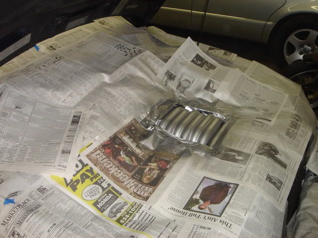
Fifth: tape off runners. Place tpe beneath the fuel rail and place engine cover back on to ensure that the tape is placed far enough down so that you cannot see it when the cover is in place.
Sixth: use duct tape and connect the newspaper to the fuel rail, and ensure that nothing is left exposed except for the intake runners.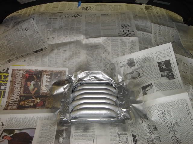
Seventh: take your can of VHT caliper paint (Color of your choice), and spray runners making sure to spray from a 12-16 inch distance, and try not to saturate them.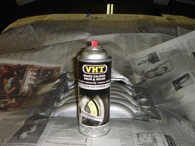
Eighth: repeat step seven at least 4 times for good results, spray thin coats, and allow ten minutes between spraying. When you have applied the desired amount of coats, allow a couple hours to dry...no need to do anything during this time.
Ninth: remove all newspaper and tape, and apply engine cover. it should come out something like this: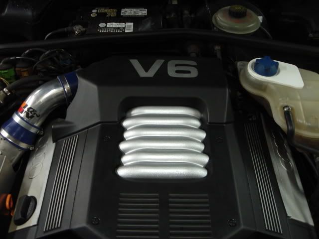
and I think this looks much cleaner than before! 
also: this will leave you PLENTY of paint to do your calipers as well....I did both and still have half a can left over.
Wednesday, April 3, 2013
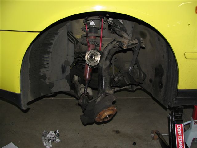
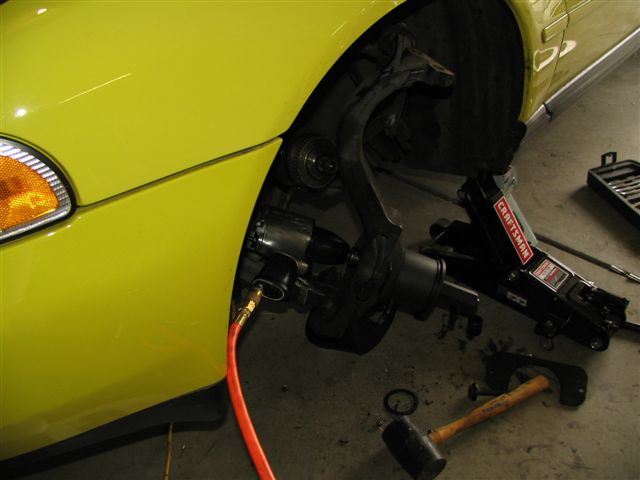
Audi A4 Front Wheel Bearing R R Using Hub Shark
bearing installed. The noise started to impede normal conversation in the car.
I ordered a hub tamer from an online store at a reasonable price. I also then ordered 2
wheel bearing kits from Blaufergneugen (sp?).
Captions follow pictures:

Picture of hub bolt, mine was a 14mm hex (Allen) head bolt.
To remove, I took the wheel off, popped out the center cap, put the wheel back on,
lowered the car * this is necessary because of the torque this bolt is speced to, more on
that later.
Remove bolt (I used a breaker bar) then jack up car that side of the car.

Basically follow the tech on how to do an A8 brake upgrade to remove the caliper,
carrier, and disc, but if you cannot figure this part out you probably should be doing a
wheel bearing change
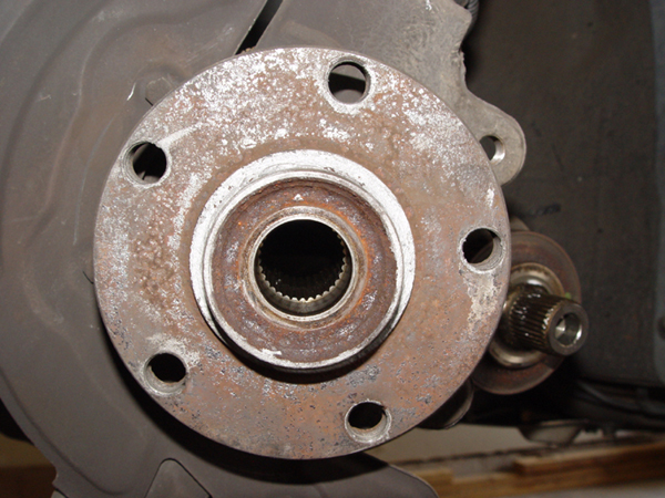
Pic shows hub with brakes removes
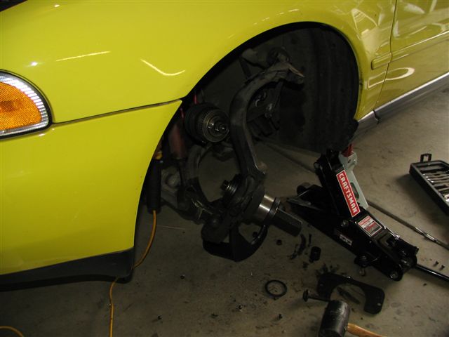
Remove bolt that connects the upper control arms to the knuckle assembly. Then tap out
the control arms.
At this point you need to turn your steering wheel all the way to the left for more
clearance. To remove the axle from the hub, put your old hub bolt in and turn a few times
to engage the threads, then tap it out with a hammer or rubber mallet. Hang it with
something, I used bungee cords.
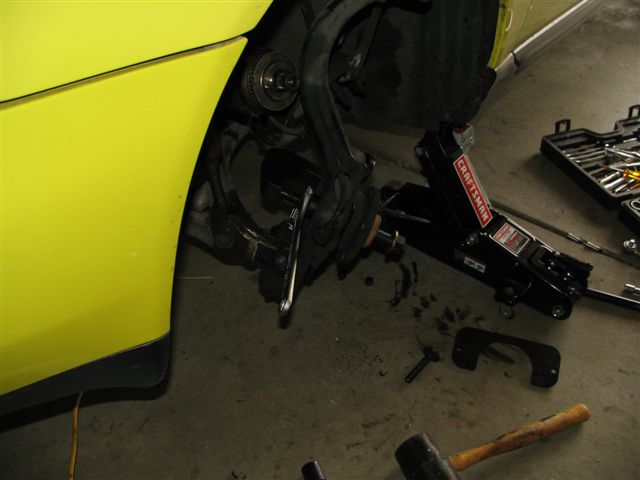
Grease your pinch bolt! Hub tamer in action now, follow the instructions word for word
in the manual of the hub tamer. Crank on the outer bolt with a 1" socket, preferably using
an impact wrench. I do believe you could do this job without one - though I sure would not
want to. The hub will slowly pull out of the knuckle/bearing.
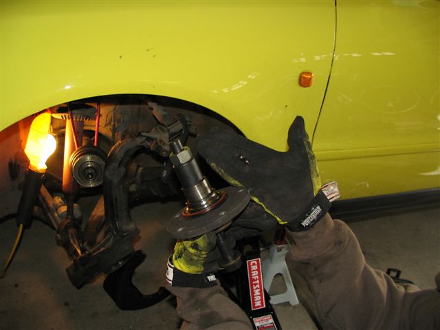
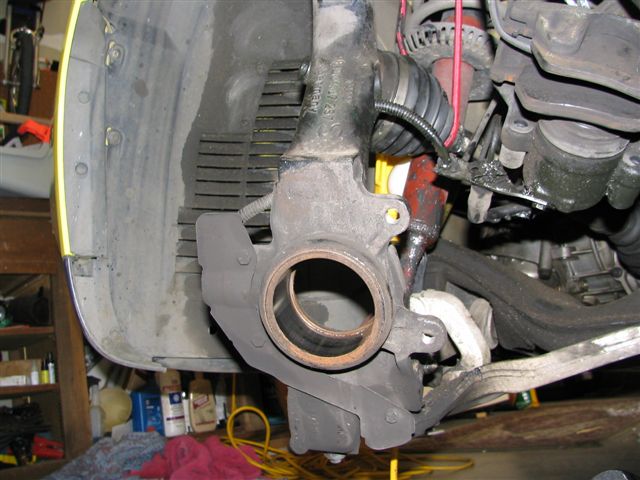
Hub removed with outer bearing race attached. The hub tamer comes with a puller that is
supposed to be able to remove this but it did not fit in the tight space between the race
and the bolt flange. I called a local shop to ask if they could do it, so I had to run out and
have it removed, 30 minutes round trip. The method they employed was crude but
effective, they took an air chisel and carefully hit the end of the bearing race, this moved
it out enough to pry it off, whatever works right?
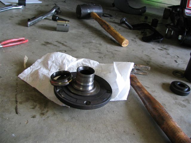
Bearing race removed from hub.
My old bearing exploded while removing the hub, I would expect this for anyone,
bearings are only pressed together and they are not held together by anything else but
pressure.
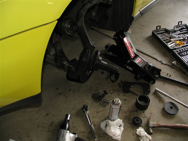
Hub tamer bearing removal assemble, let me reiterate to follow the manual to a tee,
basically at this point there is an inner disk that is pushing on the inner large diameter
bearing race. The pressure from tightening the pinch bolt moves the bearing outwards
into the large diameter cup. Outer bolt on this is something like 1 1/8 inch. I did not have
the right size socket so I just used an adjustable wrench to hold it while the impact
wrench did its thing. The threads on the hub tamer pinch bolt are fine, so it took many
turns to remove the bearing. I had to wait for my compressor to catch up at least twice
during this part. I have a 22 gallon compressor.
Bearing removed. Smile, now the fun begins.
Basically reverse of bearing removal, follow hub tamer manual to press in the new
bearing.
This is the hub tamer pressing the hub into the bearing. This was the only real gotcha I
had in the whole process. I gently tapped the hub to seat it in the bearing and my bearing
came completely apart. Luckily the grease they use is uber viscosity, it actually looked
like plastic so the bearings stayed completely intact when they fell out, I reassembled and
did not tap it in this time. Also, make sure your hub is aligned in the bearing before using
the impact wrench on it, I suggest tightening it up by hand to get it snug and aligned.
The other caveat I had was the piece they tell you to use to press the hub into the bearing
with fits over the hub. This is great to keep it aligned but it was tight, so tight that I had to
rig up the puller they gave you in the hub tamer kit to remove it. In the process I partially
pulled the hub back out. So I reversed it and tried again, this worked well.
Reassembly after the hub is back together:
Put your upper control arms back in, slide the bolt through and use the new nut supplied
in your bearing kit. Tighten to 30 ft/lbs.
In the process of using the hub tamer, I nicked the inside of the hub so I could not just
hand press the axle back into the hub. After a few iterations, I was able to get the axle in
just far enough to thread the old axle bolt to pull it in, I wrenched it tight, and removed
the old axle bolt then put the new one in. Tighten the new axle bolt to 85 ft/lbs,
do not put your axle wrenches away yet, final torque comes with the wheels all back on the ground.
Put your disc back on, caliper hangar, caliper, and wheel. Tighten your wheel bolts to
specs, 89 ft/lbs. Drop the car.
Now find a 4 foot extension for your breaker bar, you need to turn the axle bolt 180
degrees once the wheels are all down. When doing the final tightening of the axle bolt,
make sure the hex socket is ALL the way in the bolt. I stand with my leg pressing the
breaker bar assembly while I tighten the bolt to keep the socket pressed in. The bolt I got
in my kit was softer then the Audi supplied bolt I got in my CV boot kit, just an FYI.
Other notes: I did hand spin the old and new bearings in the car for comparison, the old
bearing clearly felt jagged, and when I looked at the actual bearings that fell out, they
were discolor to the point they were golden. Fresh bearings are silver.
Special Thanks to wifey for taking the pictures.
Take your quiet car for a ride. Hope this helps someone out there. I am sure that with
similar suspensions this process will work on most of the later model Audis with a bit of
modification here and there. Email me with any questions.
Job took about 3 hours which included 30 minutes out and back to the shop that got the bearing race off.
Audi A4 B5 Front Control Arm Replacement
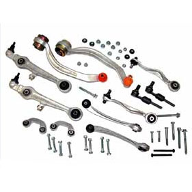
A Complete control arm set with NEW BOLTS and TREs (Tie Rod Ends)!
Yay, get ready for some work!
So your control arms are shot and your ride sounds like a 1930s Ford that squeaks all over. No problem, if the squeaking are your control arms then here is your write-up to replace them.
It is a good idea to replace the TREs as well when you this as an alignment is a very good idea after ANY suspension related work. With new TREs and CAs you wouldnt have to go back to the shop to get an alignment down the road when you replace either one.
Here is Chris Haighs write-up on how to replace the TRE. Go by his write-up on how to remove and replace the TREs and use mine for the control arms. Most Control Arm sets will cost around 500$, you get what you pay for so watch out for those 200$ sets on eBay. After all its the suspension that keeps your tuned and personalized car on the road.
Your Control arms need replacement anyways if the boot looks like this which is torn up and fluffy.
Here are some other ways to check which arm is clunking.
1) Jack car up on side thats clunking.
2) Do not remove wheel. Make sure steering rack is locked (ie key out of ignition, and turn steering wheel to lock it)
3) Grab the wheel by the 9 and 3 positions and wiggle it back and forth as it would turn by the steering. See if there is any play - there should be basically none. If you do have play, look at your control arms and feel around to see if anything is clunking or moving excessively.
Click here for a video of this test.
Click here for a video of a test for lower control arms.
In case you need to get the "knuckle assembly" aka wheel bearing housing out for a wheel bearing repair this should guide you to the removal of that as well.
Enough for the stuff here is what you need:
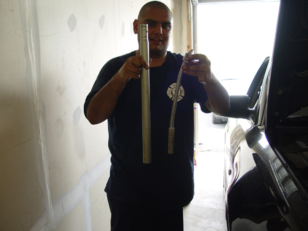
Breaker bar + extension if needed
17mm hex or smaller bigger depending on your year for the axle bolt
Ball joint removal tool
Set of wrenches
Maybe some air tools
Pb blaster or any other bolt rust breaker spray
Torque wrench
Basically a good garage should have all of the above and maybe even more
Here we go:
I am writing this guide several months after I had done the actual work. There might be some steps missing or not pictured as some of the stuff is a basic unbolt and bolt back on.
1. In order for the whole knuckle assembly to come out you need to loosen up the axle bolt that is attached to the CV boot. Its either 17mm hex (allen) or 24mm head bolt. Check that one out before you start and get the right size tool. That thing is in there TIGHT so an extension might be a very good idea as shown here:

2. Get your vehicle on JACKSTANDS not a floor jack, to many people had been injured and or killed without the use of stands. Invest 20$ in a set of them, they are cheap and safer than the hydraulic jack an article by Andy on where to jack up your car can be found here
3. Remove the wheels on both sides to expose the complete front suspension assembly.
4. Follow the previously mentioned TRE article to remove the TRE http://www.audiworld.com/tech/wheel29.shtml
I had some problems with the passenger side and ended up taking mine to the shop to get it removed. Here is what I ran into when doing my TRE
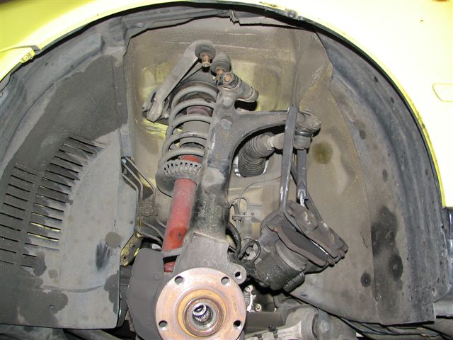
5. The front should look like this now with the TRE removed:

6. Since you will take out the complete front suspension you will should remove the brake disc and caliper as well.

In case you want to pain the caliper this is the perfect time for that as well. There are write-ups on how to remove the front brakes but here is a quick refresher.
Caliper is held onto the bracket with 2 hex bolts
Caliper is held onto the knuckle with 2 17mm IIRC bolts which are tight on there.
Brake disc is loosely held onto the knuckle with the caliper bracket, once that is loose you should be able to remove the disc. In case the disc is stuck due to rust tap it slightly with a hammer and a screwdriver like a chisel, it should come of that way.

Inspect your brake hoses for any cracking or damage, if you find some REPLACE THEM IN PAIRS! Otherwise hang the caliper now somewhere with a zip tie or have an old flowerpot of box to rest it on the ground. Dont let the caliper hang by the brake hose alone.

This is a good idea.
7. The next item on the list is the so called pinch bolt holding the upper control arms to the knuckle.

A close up

This bolt has been an issue with a lot of people to remove. If your car had been exposed to salty winter roads you will most likely have some issues removing it. I had no issues removing it but spray it with Pb blaster and follow Carsons idea as well:
/quote: Hitting the area around the pinch bolt with a hammer to loosen it up helps (read the directions on the can of PB, useful info)
You can also try turning the pinch bolt with a wrench after you get the nut off the end of it, it will either break the bolt loose or twist the head off the bolt, if it starts to twist stop what youre doing immediately. From experience, most of the time when I have to remove the pinch bolt from a steel wheel bearing housing I gotta haul out my HD Snap-On air hammer./end quote
8. After the pinch bolt is loose remove the upper control arms from the knuckle, they are just "pushed" in. With road salt and dirt in them they could be very had to remove so a tool like this might be helpful:
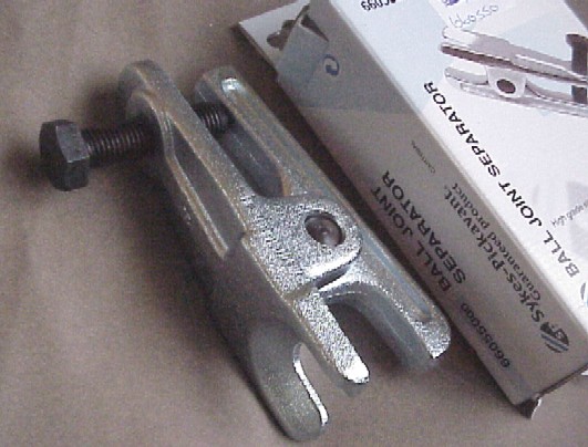
These are ball joint separators and range from 11$ to 100$ in price, you get what you pay for in quality. Your local car place might have them for rent as well.
9. Now its time to loosen that tight axle bolt up some more. When I did the work on Kevins car I forgot to loosen them up with the car on the ground. I ended up breaking the bolt loose in the air and bended the breaker bar pretty good. So dont forget to loosen that bolt up before you lift the car into the air! Here are our results:

10. With the bolt loose. Tap it slightly with a hammer to "push" the whole CV joint out of the knuckle. I turned the bolt a like 2 turns, tapped it with hammer back to the bearing and turned again and so on... be gentle as the wheel bearing sits in the knuckle assembly. Depending on the mileage that you have on the car its a good idea to replace both bearings as well since those are known to fail at some point and time.
You should be here now:

The knuckle is still connected to the car by the lower control arms while everything up top is loose and removed.
11. The upper control arms are attached to the strut mounting plate and we were unable to remove the bolts because of tightness, we ended up removing the plate. Its attached with 3 bolts as shown here:

Remove those bolts and the top will become loose. In order to take the strut tower out you will have to remove the lower bolt that is attached to the control arm. Also be very careful to not over torque those when you reinstall the whole thing.
The upper control arms showing some damage on the boots when we wedge something in there to remove them.
Remove the old arms either on the car or on the mounting plate.
12. Here is a picture of the lower control arm assembly connected to the knuckle. Now comes the removal of the ABS sensor (already loose in the 1st picture) if you want to. The abs sensor does NOT have to be removed but its a good idea of cleaning it while you in here All that is needed is to disconnect the sensor cable.


In the top picture it shows the ABS sensor already removed. The abs sensor is just "pushed" into the whole where it sits the rest of its live and gets exposed to rust so it might be a bit hard to remove, but ours just pulled right out.
The connector for the sensor is stashed behind the fender well as seen here:

There is a rubber plug that you need to pull out, when doing so you will expose the connector, disconnect it and tuck it somewhere into the top of the control arms as shown.
13.The only thing that is holding the knuckle now to the car are all the lower bolts from the control arms and the reversed C sway bar link and the strut/suspension.

The rear control arm goes in from the top while the front control arm is pushed into the knuckle from the bottom. The reversed C is the sway bar link and connects to the control arm. Those are basic unbolt and removal steps now.
That is how the arms will look with the knuckle removed

You might need to use the joint tool again as the lower arms might be even tighter than the uppers. I had no issues with either, but this tool with be a life saver!
Unbolt those and take the knuckle assembly out

14. If you went the way that we did you car will look like this now:


15. In case you cant get one of the bolts out and you are stuck like this:

You will need to loosen up the green circled plate holding the sub frame on the side. No need to totally remove me but loosening it up will give you enough clearance to remove the bolt.

We loosened our bolt barely an inch and it worked

Remove lower front and lower rear control arms you complete the removal of all the control arms

that is it! Reinstallation in the reverse order!

Couple of notes in the end:
While doing this you can do several things:
Repaint Calipers
Change out brake hoses to stainless steel ones
Change out brake pads and rotor
Upgrade the front brakes to A8 rotors and TT carriers
Spray paint the whole fender well BLACK again while everything is removed for a cleaner look
Flush your brake fluid out
Oil change
Engine mount replacement
DV replacement
Just to mention a few things!
Torque Specs for reassembly:
Kevin always get on me for not using a torque wrench so here are the specs taken from Bentley Manual
Upper front; 50 Nm + 1/4 turn into mounting bracket
Upper rear; 50Nm + 1/4 turn into mounting bracket
Upper pinch bolt; 40 Nm (not TRE pinch bolt)
Lower front; 80 Nm + 1/4 turn into subframe
Lower rear; 90 Nm +1/4 turn into subframe
Lower control arms into steering knuckle; 100 Nm
Mounting bracket (shock tower assembly)
Upper bolts from inside the engine bay; 75 Nm
Lower nut and bolt into control arm; 90 Nm
Sway bar end link;
Lower connection to the sway bar; 100 Nm
Upper connection into the control arm; 40 Nm + 1/4 turn
Rear Sub Frame; Large Bolt 110 Nm + 1/4 turn small bolts; 23 Nm
A few tips for the reassembly. Dont torque down your new control arms "dry" that means without being attached to the knuckle assembly when reinstalling. Doing so will make it hard to move them around as needed.
USE antiseize on the following parts: Pinch bolt, TRE threads and the bolt holding the TRE into the knuckle.
CPP has a set of full metal suspension parts that are likely to last a whole lot longer than anything else. Their website with all the information except prices is here
Kris Hansen added grease fittings to his arms in terms of long term life. He has those included in his Upper Control arm write-up found on his website
Passatworld (VW Passat and the Audi A4 are basically the same mechanically) has a small Control Arm Faq that is Listed on the website
There is an active recall on the front lower control arm that will be replaced for free if certain conditions are met found Under this post